
Torsion springs are key in utilizing torsion force to store and release energy in mechanical systems, from household items to complex machinery. Their ability to exert torque when twisted makes them essential for applications needing rotational motion, highlighting their role in engineering and design.
This article examines torsion spring mechanics, focusing on torsion spring force principles, material selection, and design impacts on performance. It emphasizes the importance of calculating spring rate, torsional stress, and shear stress in improving torsion spring durability and functionality.
Short on time? Skip the hand calculations and try our torsion spring calculator — enter your specs to get spring rate, torque, leg-tip force and bending stress instantly.
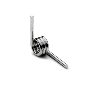
Fundamentals of Torsion Spring Force
Understanding the fundamentals of torsion spring force involves delving into the mathematical and mechanical principles that govern their operation. Here, we break down these principles into more digestible components:
- Key Calculations for Torsion Spring Mechanics:
- Spring Constant (KT): The stiffness of a torsion spring is quantified by its spring constant (KT), calculated as KT = (E × d^4) / (64 × D^3), where E represents the modulus of elasticity, d is the wire diameter, and D is the coil diameter.
- Spring Torsion Angle (φ): This angle can be determined using the formula φ = (8 × KT × L × ΔD) / (G × d^4), with G being the modulus of rigidity, L the length of the spring, and ΔD the change in diameter.
- Spring Stress (σ): The stress experienced by the spring can be calculated as σ = (32 × M) / (π × d^3), where M is the moment or torque applied.
2. Determining Spring Characteristics:
- Spring Index (c): This is a ratio of the coil diameter (D) to the wire diameter (d), calculated as c = D/d. It’s a crucial parameter for understanding the spring’s design and its flexibility.
- Number of Active Turns (Na): The active turns contribute directly to the spring’s ability to store energy, calculated as Na = I + βrad/(2π) or Na = I + βdeg/360, where I is the initial number of turns, and β represents the angle of twist in either radians or degrees.
3. Applications and Durability:
- High Durability and Longevity: Torsion springs are recognized for their robustness and extended service life, making them ideal for applications where longevity is critical.
- Mechanisms Requiring Rotational Force: Due to their ability to generate high torque or rotational force through a twisting motion, torsion springs are perfectly suited for mechanisms that require rotational movement or resistance.
These principles highlight the intricate balance between material properties, geometric design, and mechanical forces that enable torsion springs to function effectively. Understanding these fundamentals is crucial for anyone involved in the design, selection, or analysis of torsion springs in mechanical systems.
Calculating Spring Rate for Torsion Springs
Calculating the spring rate for torsion springs is a fundamental aspect of ensuring their effective performance in various applications. This process involves several key formulas and considerations:
- Spring Rate Calculation:
- The basic formula for calculating the spring rate (R) is given by: R = Ed^4 / 10.8 DN. Here, E represents the modulus of elasticity of the material, d is the wire diameter, D is the mean coil diameter, and N is the number of active coils.
- For a more specific application, the spring constant (k) can be calculated using: k = P*M/Deg, where P is the force applied, M is the moment or torque, and Deg is the degrees of deflection.
- To determine the spring rate per degree, one can divide the calculated spring rate by 360 degrees, providing a measure of the spring’s resistance to torsion per degree of twist.
2. Torque and Deflection Calculations:
- To find the torque required for a desired degree of deflection, multiply the desired degrees of deflection by the spring rate: Torque = Desired Deflection * Spring Rate.
- Conversely, to calculate the degrees of deflection achieved with a certain amount of torque, divide the torque by the spring rate per degree: Degrees of Deflection = Torque / Spring Rate per Degree
3. Adjustments for Spring Design:
- Changes in leg length can affect the torsion spring’s performance. The formula for adjusting the leg length is: (Leg Length New – Leg Length Old) * Object Force (N) = Degree of Rotation (Max) * Spring Constant (N mm/°) . This calculation is essential for customizing the spring’s performance to specific requirements.
- It’s also crucial to calculate the free length after deflection to prevent major failure. This involves calculating the increase in coils due to deflection as N’ = N + (Deflection / 360), and then calculating the new total free length with deflection as FL’ = (N’+1) X (Wire Size or Axial Width).
These calculations are key to designing, selecting, and utilizing torsion springs effectively. By understanding and applying these formulas, engineers and designers can ensure that torsion springs are perfectly suited to their intended applications, thereby enhancing the performance and longevity of the mechanical systems they are a part of.
Quick Reference: Common Spring Materials
| Material | Elastic modulus (E) | Typical use |
|---|---|---|
| Music wire (ASTM A228) | 207 GPa (30,000 ksi) | Highest strength, general precision springs |
| Stainless steel 302 (ASTM A313) | 193 GPa (28,000 ksi) | Corrosion resistance, food/medical |
| Phosphor bronze | 103 GPa (15,000 ksi) | Electrical conductivity, non-magnetic |
| Inconel X-750 | 214 GPa (31,000 ksi) | High temperature up to ~700°C |
Worked Example: Calculating Torsion Spring Torque Step by Step
Theory is useful; numbers are better. Here is a complete calculation for a typical music-wire torsion spring.
Given: music wire (ASTM A228), wire diameter d = 2.0 mm, mean coil diameter D = 20 mm, active coils Na = 5, elastic modulus E = 207,000 N/mm².
Step 1 — Spring rate per 360°:
k = E × d⁴ / (10.8 × D × Na) = 207,000 × 16 / (10.8 × 20 × 5) = 3,067 N·mm per revolution (8.52 N·mm per degree).
Step 2 — Torque at 90° deflection:
T = 8.52 × 90 = 767 N·mm (0.77 N·m).
Step 3 — Force at the leg:
With a 50 mm leg, F = T / leg length = 767 / 50 = 15.3 N at the leg tip.
A note on units: torsion spring rate is torque per angle — N·mm/°, lb-in/deg, or N·m/rad. Never confuse it with compression spring rate (force per distance). If a drawing gives you kg/s², that is simply N/m expressed differently — convert before you calculate.
Zigoal Torsion Spring Calculator
Skip the hand calculations: the Zigoal torsion spring calculator gives you spring rate, torque at a given deflection angle, leg tip force and bending stress as you type, in metric or imperial units.
Factors Influencing Torsion Spring Force
Factors influencing the torsion spring force are multifaceted, with each aspect playing a crucial role in the spring’s overall performance. Understanding these factors is essential for effective design and application:
- Material Selection:
- The specific material used significantly impacts the spring force, as different materials possess unique properties and advantages. For instance, some materials may offer higher tensile strength or better corrosion resistance, which are vital for certain applications.
- Temperature Sensitivity: Materials react differently under temperature variations; high temperatures can cause materials to expand, reducing tension and weakening the spring. Conversely, low temperatures can increase stiffness and reduce flexibility, potentially affecting the spring’s functionality.
2. Design and Operational Parameters
- Max Safe Travel and Max Load: These are critical parameters for ensuring the safe operation of the torsion spring. Exceeding these limits can result in spring failure, affecting the safety and reliability of the mechanism.
- Spring Inner Diameter and Potential Binding: A reduction in the inner diameter during operation can lead to binding, which impedes the spring’s function. It’s essential to consider this factor to avoid operational issues.
- Minimum Hysteresis (Load Loss): This refers to the loss of load due to internal friction within the spring material, affecting the spring’s efficiency. Minimizing hysteresis is crucial for maintaining performance.
- Clearance and Body Length Considerations: Adequate clearance between the mandrel and the torsion spring is necessary to prevent friction and wear, while an increase in body length when deflected must be accounted for in the design to ensure proper functionality.
- Temperature Conditions: The choice of material for torsion springs is particularly crucial as it directly affects the spring’s performance across various temperature conditions. Materials that are not suited to the operational temperature range can lead to premature failure or reduced efficiency.
In summary, the performance and reliability of torsion springs are influenced by a combination of material properties, design considerations, and environmental factors. Each of these aspects must be carefully evaluated during the design and selection process to ensure that the torsion springs meet the required specifications and operate effectively within their intended applications.
The Role of Wire Diameter in Torsion Spring Force
Understanding the pivotal role of wire diameter in torsion spring force is essential for optimizing spring performance in mechanical applications. The influence of wire diameter on torsion springs can be summarized as follows:
- Linear Relationship with Spring Rate:
- The relationship between wire diameter and spring rate is direct and linear, meaning as the wire diameter increases, so does the spring rate. This is a fundamental principle in torsion spring mechanics, underscoring the importance of precise wire diameter selection.
2. Impact on Spring Characteristics:
Stiffness and Load Capacity:
- A thicker wire results in a stiffer spring, capable of bearing higher loads. However, this comes at the cost of reduced flexibility.
- Conversely, a thinner wire offers greater flexibility but at a lower load capacity and reduced stiffness.Durability and Lifespan:
- Wire gauge, which indicates the thickness of the wire, plays a significant role in the spring’s overall strength. A higher wire gauge means a thicker wire, contributing to increased durability and a longer lifespan of the spring.
3. Design and Performance Considerations:
- Spring Constant and Moment Calculation:
- The spring constant, a crucial factor for calculating the moment or the force applied to the spring, is directly influenced by the wire diameter. The moment itself is determined by multiplying the force by half the leg length.
- Adjusting Torsion Force:
- The torsion force, which can be calculated by dividing the weight of the object by the moment, is also affected by changes in wire diameter. Adjustments in wire diameter, along with spring diameter and number of active turns, can significantly alter the Nmm/° of a torsion spring, thus modifying its force output.
- Design Around Pivot:
- It’s crucial to ensure that the inner diameter of the loaded spring does not shrink below the diameter of the pivot when designing a torsion spring around a pivot. This consideration prevents operational issues such as binding, which can impair the spring’s functionality.
These insights into the role of wire diameter in torsion spring force highlight the intricate balance between material selection, geometric design, and mechanical forces. By carefully considering wire diameter during the design process, engineers can enhance the performance, durability, and application suitability of torsion springs.
Torsion Spring Rate and Its Significance
Torsion springs, by design, offer several intrinsic advantages that make them preferable in specific applications, especially when compared to extension springs. Their compact design and increased durability are prime examples of such advantages. Understanding the significance of the torsion spring rate and its calculation is crucial in harnessing these benefits effectively.
- Spring Rate Calculation:
- The torsion spring rate, denoted as (R), is calculated using the formula: (R = \frac{Ed^4}{10.8DN}).This formula encapsulates the direct relationship between the spring rate and the wire diameter (d), mean coil diameter (D), number of active coils (N), and the modulus of elasticity of the material (E). The spring rate is a critical determinant of the spring’s performance, dictating how much force the spring can exert per unit of radial travel.
2. Importance of Spring Constant:
- The spring constant, expressed in Nmm/°, is pivotal in torsion spring design. It defines the force exerted by the spring per 360 degrees of radial travel. This constant is essential for ensuring that the spring delivers the required force output without succumbing to deformation or failure under load.
3. Adjusting Spring Rate with Leg Length:
- Adjusting the leg length of a torsion spring necessitates recalibration of the spring rate to prevent structural compromise. For instance, altering the leg length to 120 mm on a TS103020L spring necessitates adjusting the spring constant to 127.8 N mm/° to maintain a maximum twist of 70 degrees. Failure to appropriately adjust the spring rate in response to changes in leg length can lead to functional inefficiencies, where the spring may not operate as intended.
These considerations underscore the critical role of the torsion spring rate and spring constant in the design and functionality of torsion springs. By meticulously calculating and adjusting these parameters, designers and engineers can optimize torsion springs for a wide range of applications, leveraging their compactness and durability to achieve desired mechanical outcomes.
Leg Length & Leg Configurations: Small Changes, Big Force Differences
The importance of leg length in torsion springs significantly influences their functionality and performance in mechanical applications. This can be broken down into key areas:
- Leg Configuration and Force Impact:
- Leg configuration directly affects the torsion spring’s force, with the leg length playing a pivotal role in determining the load or torque required for energy storage within the spring.
- Shorter legs necessitate a higher torque input to bend the coils, whereas longer legs require less force due to the leverage principle, standard in moment theory.
- Performance Influences:
1. Leg Length vs. Torque Requirement: The leg length of a torsion spring is crucial in affecting its performance, specifically influencing the force required to turn the spring. An increase in leg length decreases the force needed to achieve rotation, enhancing efficiency in applications requiring precise control over movement and force application.
2.Example of Leg Length Impact: Taking the TS103020L spring as an example, a spring constant of 95.86 N mm/° with a leg length shortened to 50 mm results in a maximum moment of 3,727.89 N and rotation of 38.89 degrees. This demonstrates the significant impact leg length adjustments can have on a spring’s force output and rotational capabilities.
- Calculations and Customizations:
- The moment, a critical factor in determining the torsion force, is calculated by multiplying the force by half the leg length. This calculation underscores the importance of leg length in the overall performance and application of torsion springs.
- Torsion force calculations further emphasize the role of leg length, where the force is determined by dividing the weight of the object by the moment. Adjustments in leg length, therefore, directly influence the torsion force achievable, enabling customization for specific project needs.
- Customization options for the legs of the spring, including bends, twists, hooked, or looped ends, provide additional flexibility in design and application, allowing torsion springs to be tailored to meet the unique requirements of various projects.
These insights highlight the crucial role of leg length in the design and functionality of torsion springs, demonstrating the need for careful consideration and calculation during the design phase to ensure optimal performance and application suitability.
Beyond length, the configuration of the legs changes how force is delivered: straight legs give the cleanest moment arm, radial legs suit tight housings, axial legs work along the coil axis, and tangential legs reduce stress concentration at the bend. When you specify a torsion spring, always define both length and configuration — custom spring prototyping the wrong leg style is one of the costliest avoidable mistakes.
Winding Direction: Why It Changes Everything
A torsion spring only works in one rotational direction. Wind it the wrong way and the coil tightens instead of opening — or worse, it takes a set on the first cycle and never recovers its rate.
- Right-hand vs left-hand wind is defined by the direction the coil spirals when viewed from the front. It must match the direction of the applied load.
- Loading a spring against its wind direction increases coil diameter and reduces stress; loading with the wind closes the coil down, raising stress sharply and risking coil bind.
- When you request a quote, always specify wind direction along with your torque requirement. A drawing without it is incomplete — this is one of the most common causes of prototype rework we see at Zigoal’s torsion spring shop.
Material Types and Their Impact on Torsion Spring Force
Material selection plays a pivotal role in determining the performance characteristics and suitability of torsion springs for specific applications. The primary materials used in the manufacturing of torsion springs include:
- Steel:
- Characteristics: Known for its high strength and durability.
- Applications: Suitable for applications where high tensile strength is required to handle significant mechanical stresses.
2. Stainless Steel:
- Characteristics: Offers excellent corrosion resistance, making it ideal for use in environments where the spring may be exposed to corrosive agents.
- Applications: Frequently used in medical devices, marine applications, and any setting where the prevention of rust is critical.
3. Other Alloys:
- Characteristics: Each alloy has unique properties, such as high temperature resistance or specific magnetic properties, that can be leveraged for specialized applications.
- Applications: Chosen based on the specific requirements of the application, such as temperature sensitivity or magnetic field interaction.
The choice of material is critical and should be determined based on the specific requirements of the application. For instance, while steel torsion springs provide the strength needed for heavy-duty applications, stainless steel variants are indispensable in scenarios where environmental conditions could lead to corrosion, potentially compromising the spring’s integrity and functionality. Similarly, the selection of other alloys allows for the customization of torsion springs to meet the demands of highly specialized applications, where generic materials may not provide the necessary performance characteristics.
Not sure which alloy fits your environment? See our torsion spring material options and the full spring material selection guide.
Design Considerations for Torsion Springs
Design considerations for torsion springs are multifaceted, incorporating various parameters that influence their functionality and performance. These considerations are crucial for ensuring that torsion springs meet the specific requirements of their intended applications. Key design considerations include:
- Coil Characteristics:
- Coil Pitch and Length:The coil pitch and length significantly impact the spring’s compression and extension characteristics. A smaller coil pitch and shorter length result in a stiffer spring, offering less flexibility but greater resistance to forces. Conversely, a larger coil pitch and longer length yield a softer spring, providing greater flexibility and adaptability to varying loads.
- **Surface Finish:A smooth and polished surface finish is essential for reducing friction between the coils, facilitating smoother movement, and enhancing the spring’s durability. Polished finishes can further improve corrosion resistance, extending the lifespan of the spring in corrosive environments.
- Spring Configuration:
- Leg Configurations: The configuration of the torsion spring legs plays a vital role in its performance under different loading conditions. Adjustments in leg configurations can significantly impact the force exerted by the spring, making it a critical consideration in the design phase.
- Wind Direction: The direction in which the torsion spring is wound (left-hand or right-hand) determines the direction of the torsion force generated (clockwise or counterclockwise). This aspect is crucial for applications where the direction of force application is a key operational parameter.
- Operational Parameters:
- Max Safe Travel and Load: Designers must specify the maximum safe travel and load the spring can handle without experiencing stress, fatigue, or failure. This parameter is determined by considering the torsion spring constant and is essential for ensuring the safety and reliability of the spring in its application.
- **Inner Diameter and Clearance: It’s important to consider the reduction in inner diameter during deflection and ensure proper clearance over the supporting rod. This prevents potential binding and ensures the spring functions smoothly within its operational environment.
These design considerations underscore the importance of a thorough and detailed approach to torsion spring design. By carefully evaluating and adjusting these parameters, engineers and designers can create torsion springs that are highly customizable, versatile, and suited to a wide range of applications. The ability to tailor torsion springs according to customer specifications, including various after-treatments like chrome plating and cleanroom packaging, further enhances their applicability across different industries.
Stress, Fatigue Life & Temperature: Where Formulas Meet Reality
The basic formulas assume ideal conditions. Real springs live in messier ones.
- Bending stress is the real limit, not torque. Check it with S = 32M / (πd³), corrected by the Wahl curvature factor — inner-coil stress runs significantly higher than the straight-wire formula suggests.
- Fatigue life drops fast past ~70% of maximum safe deflection. If your mechanism cycles millions of times (door systems, actuators), design to a lower stress and say so on the drawing.
- Temperature changes everything: elevated heat relaxes music wire (consider stainless or high-temp alloys above ~120°C), while cold increases brittleness risk in some materials.
Watch the diameter change
As a torsion spring deflects, its coil diameter shrinks (loaded with the wind) or grows (against it). Always check clearance against the shaft or housing at full deflection — interference here is a silent killer.
Where Torsion Spring Force Matters: Real-World Applications
Torsion spring force does quiet work in places you touch every day:
- Garage doors & access systems — counterbalancing hundreds of kilograms with controlled torque.
- Automotive & robotics — trunk hinges, throttle bodies, and robotic joints where consistent return force matters.
- Medical & electronics — clips, battery contacts, and precision mechanisms where force must stay stable over millions of cycles.
- Industrial machinery — counterbalances, tensioners, and safety returns.
Torsion vs extension vs compression — a 30-second guide
Torsion springs deliver torque over an angle; extension springs deliver pull over a distance; compression springs deliver push over a distance. If your mechanism rotates, you almost certainly want torsion — converting a linear spring to do a rotary job wastes space and force. See our full range of custom springs.
Conclusion
This exploration into torsion springs has revealed key insights into their mechanics, design considerations, and material impacts on performance. Understanding these elements is crucial for optimizing their use in various applications, highlighting the importance of detailed engineering and design. This guide underscores the vital role of torsion springs in mechanical systems and serves as a foundation for leveraging torsion forces effectively.
Need Custom Torsion Springs Built to Your Spec?
Send us your torque requirement, deflection angle, leg configuration and wind direction — Zigoal will engineer it, prototype it, and manufacture it to your drawing.
Frequently Asked Questions
Why does a torsion spring break?
Most failures come from three causes: over-stressing past the material’s fatigue limit (often from deflecting beyond the design angle), loading against the wind direction, or coil bind — the coils jamming solid at full deflection. Sharp bends at the legs are another classic failure point. Designing with proper stress correction and a realistic safety margin prevents nearly all of these.
How many turns should I wind a torsion spring?
Wind only within the design deflection angle, not a fixed number of turns. Exceeding the maximum safe angle takes a permanent set and the spring never returns to its original rate. As a rule of thumb, stay under 70% of the theoretical maximum for any application that cycles repeatedly, and always verify against the stress calculation — not guesswork.
Does the length of a torsion spring matter?
Yes — body length (number of active coils) directly sets the spring rate: more coils mean a softer spring for the same wire and coil diameter. Leg length matters too, but differently: it sets the moment arm, converting torque into force at the leg tip. Change either one and you must recalculate.
What do the numbers mean on torsion springs?
Typical markings or spec callouts include wire diameter, outer or mean coil diameter, number of active coils, leg length and configuration, wind direction (RH/LH), and sometimes the rated torque at a given angle. If you are replacing a spring, measure all of these — or send the old spring to us and we will reverse-engineer it.
What is the difference between torque and torsion?
Torsion is the twisting action applied to the spring; torque is the rotational force the spring exerts in response, measured in N·mm or lb-in. Think of it this way: torsion is what you do to the spring, torque is what the spring does back.
How do I calculate the torsion constant (k)?
Use k = E × d⁴ / (10.8 × D × Na) for the rate per 360° of deflection, where E is the elastic modulus, d the wire diameter, D the mean coil diameter, and Na the active coils. Divide by 360 for the per-degree rate. See the worked example above for a complete calculation with real numbers.
What is torsional stiffness?
Torsional stiffness is the same thing as torsion spring rate (k): how much torque is needed to rotate the spring by one unit of angle. Higher k means a stiffer spring — more torque per degree. It is set by wire diameter, coil diameter, active coils, and material, in that order of sensitivity.
How does temperature affect torsion spring performance?
Heat relaxes spring materials and lowers the effective rate — music wire starts losing temper above roughly 120°C. Cold makes some materials brittle. For high-temperature service, specify stainless steel, Inconel, or other high-temp alloys, and tell your manufacturer the operating range: it changes both material choice and the safety factors.
How do I determine the maximum safe deflection angle?
Calculate the bending stress at your deflection using S = 32M/(πd³) with the Wahl correction factor, then compare against the material’s allowable stress for your required cycle life. For infinite-life designs, stay well under 50% of tensile strength. When in doubt, prototype and cycle-test — paper calculations are a starting point, not a guarantee.
What’s the difference between active and total coils?
Active coils are the coils free to deflect and contribute to the spring rate; total coils include the end coils that form the legs and don’t flex. Only active coils go into the rate formula — using total coils is one of the most common calculation mistakes we see on customer drawings.
Glossary
Spring rate (k): torque required per unit of deflection angle.
Active coils (Na): coils free to deflect; the only coils counted in rate formulas.
Wind direction (RH/LH): the spiral direction of the coil; must match load direction.
Leg: the straight arm extending from the coil body; its length sets the moment arm.
Coil bind: coils jamming solid at full deflection — a design failure, not a feature.
Wahl factor: curvature correction applied to bending stress at the inner coil surface.


